
 EN
EN



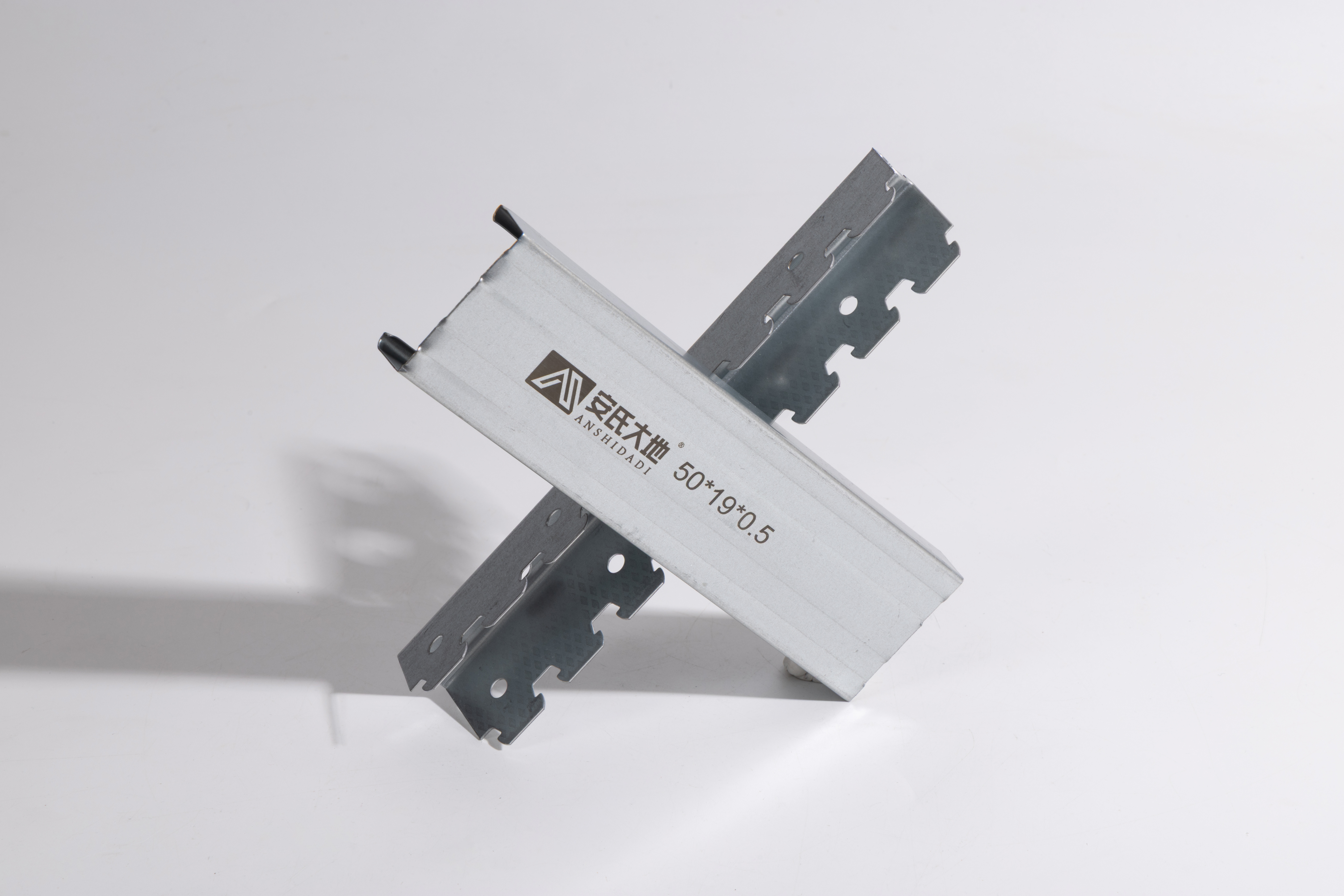
Suspended systems require careful engineering to ensure long-term safety and performance. The foundation of any reliable suspended structure depends on the strength and capacity of its primary support components. A metal stud serves as the backbone of these systems, providing the structural integrity necessary to handle dynamic and static loads over decades of operation. Understanding how a metal stud performs under load is essential for architects, engineers, and construction professionals who design and implement suspended solutions in modern buildings.
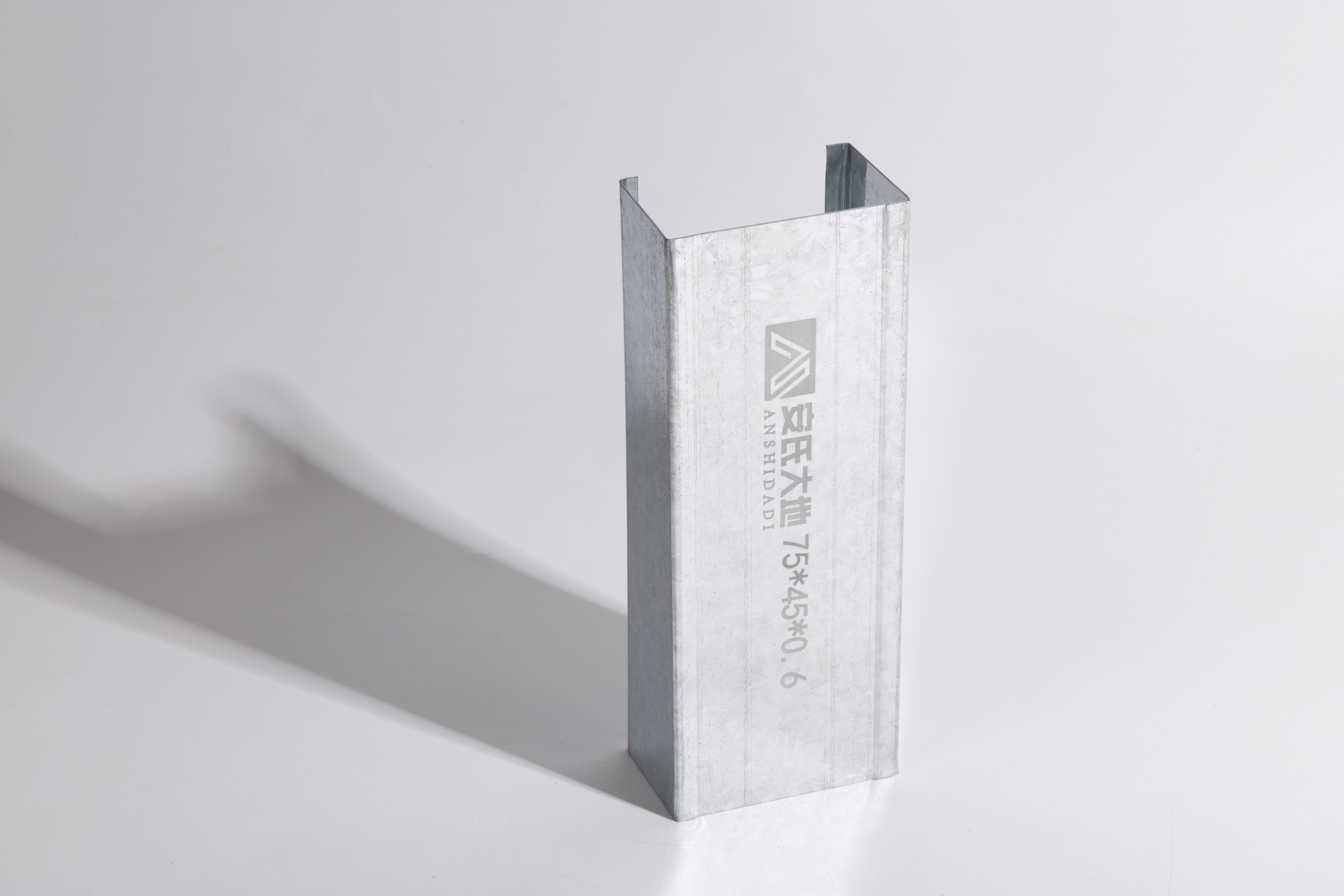
The engineering behind suspended systems has evolved significantly over the past two decades. Modern metal stud configurations are designed using advanced materials science and computational modeling to optimize both strength and cost-efficiency. A metal stud in today's suspended systems must not only carry its rated load but also accommodate thermal expansion, vibration, and building movement. This article explores the real-world load bearing capabilities of metal stud frameworks, the factors that influence their performance, and how to select the right configuration for your specific application.
Metal Stud Structural Design and Load Distribution
Understanding Metal Stud Composition and Geometry
A metal stud used in suspended systems is typically manufactured from cold-rolled steel or aluminum alloy, depending on the application requirements and environmental conditions. The cross-sectional geometry of a metal stud directly determines its moment of inertia and therefore its bending resistance. Common profiles include C-channel, track systems, and specialty shapes engineered specifically for suspended load applications. The wall thickness and flange width of each metal stud profile are calculated to provide optimal strength-to-weight ratios, enabling longer spans and higher loads without excessive material expense.
The manufacturing process for a metal stud involves precision rolling or forming to achieve consistent dimensional tolerances. These tolerances are critical because variations in thickness or width can significantly affect how a metal stud performs under real-world loading conditions. Professional installers must verify that each metal stud meets specified dimensions before installation. When a metal stud is properly formed and dimensionally consistent, it delivers predictable load bearing performance and integrates seamlessly with other suspended system components.
Load Path Analysis in Suspended Frameworks
Suspended systems distribute loads through interconnected members, with each metal stud contributing to the overall structural response. The load path begins at the ceiling or building structure, transfers through the metal stud framework, and ultimately connects to primary support points or the building core. A metal stud in the secondary tier of a suspension system may carry combined loads from multiple connection points, requiring careful calculation of cumulative stress. Engineers use finite element analysis to model how loads flow through each metal stud member and ensure no single component becomes a failure point.
The connections between metal stud members are as critical as the members themselves. A properly designed metal stud connection transfers loads smoothly while minimizing stress concentration. Bolted, welded, or mechanical fastening methods each offer different advantages depending on whether the metal stud system needs to be temporary or permanent, adjustable, or fixed. When designing the load path through a metal stud framework, engineers must account for how each connection type influences the overall system behavior under both normal and extreme loading scenarios.
Capacity Factors and Real-World Performance Metrics
Allowable Load and Safety Margins
The rated capacity of a metal stud is expressed in terms of allowable load, which is the maximum safe load that the metal stud can carry over an extended period without permanent deformation. This allowable load is typically 40 to 60 percent of the material's ultimate tensile strength, depending on safety codes and application requirements. For suspended systems, a metal stud's allowable load rating accounts for fatigue, vibration, and the cumulative effect of repeated loading cycles. Building codes require that every metal stud in a suspended system operate well below its yield point, ensuring that any metal stud remains elastic and returns to its original shape after load is removed.
Suspension system engineers build in multiple layers of safety when specifying a metal stud for critical applications. Redundancy is a fundamental principle, meaning that failure of any single metal stud does not cause system collapse. When a metal stud is sized for actual load plus 50 to 100 percent additional capacity, the system remains functional even if that metal stud experiences unexpected stress concentration or minor defects. This conservative approach has proven effective in real-world suspended systems that have operated for 50 years or longer.
Deflection and Performance Limits
While a metal stud can technically support a certain load without yielding or failing, its deflection under that load must also be controlled. Excessive deflection of a metal stud can cause operational problems, including misalignment of suspended equipment, floor vibration, or stress on nonstructural connections. Building codes typically limit the deflection of a metal stud under its full design load to a span-dependent ratio, commonly between 1/240 and 1/360 of the span length. A metal stud that meets load bearing requirements but exhibits excessive deflection will need to be upgraded to a larger profile or supplemented with additional bracing.
Vibration response is another critical performance metric for metal stud systems in suspended applications. When a metal stud system experiences intermittent loading or environmental vibration, the natural frequency of that metal stud determines its response amplitude. A well-designed metal stud configuration avoids resonance with common vibration frequencies in the building, typically between 1 and 10 hertz. Damping materials and careful sizing of the metal stud framework help control vibration and ensure user comfort in spaces where suspended systems are present.
Material Selection and Environmental Considerations
Steel Versus Aluminum Metal Stud Options
Steel remains the dominant material for heavy-duty suspended systems because a steel metal stud delivers maximum strength per unit weight and cost. A galvanized steel metal stud resists corrosion in most indoor environments and requires minimal maintenance. However, in corrosive environments such as parking garages, salt spray zones, or chemical storage areas, a stainless steel metal stud or aluminum metal stud may be necessary despite higher material cost. The choice between steel and aluminum metal stud systems depends on load requirements, span length, environmental exposure, and budget constraints.
Aluminum metal stud systems offer lighter weight and excellent corrosion resistance, making them ideal for certain applications. However, aluminum has lower stiffness than steel, so an aluminum metal stud must be larger or more heavily reinforced to achieve the same deflection performance as a comparable steel metal stud. Cost-benefit analysis often favors steel for standard suspended systems, while specialized applications or extremely corrosive environments justify the premium cost of aluminum or stainless steel metal stud components.
Environmental and Long-Term Durability Factors
The long-term performance of a metal stud depends on material compatibility with its environment and protection against degradation. Galvanizing, powder coating, or paint systems protect a steel metal stud from moisture and oxygen exposure. In high-humidity or wet environments, periodic inspection and recoating of the metal stud framework prevent rust development that could compromise capacity. Documentation of the metal stud material grade, protective coating type, and installation date enables proper maintenance scheduling and risk assessment over the building's lifespan.
A metal stud system that was installed correctly but subjected to unexpected environmental stress may require reinforcement or component replacement. Seismic events, extreme wind loads, or vibration from heavy equipment can reveal weaknesses in metal stud connections or sizing assumptions. Periodic professional inspection of suspended metal stud systems, especially in critical applications, identifies degradation before it affects safety or operability. Building owners who invest in metal stud system maintenance protect their asset value and ensure continued reliable performance.
Design Best Practices and Installation Standards
Proper Spacing and Bracing of Metal Stud Members
The spacing between metal stud members in a suspended framework directly affects the load that each metal stud must carry. Closer spacing distributes load over more members, reducing the stress in each metal stud and enabling the use of smaller profile sizes. However, closer metal stud spacing increases material quantity and installation labor. Engineers optimize metal stud spacing by balancing structural efficiency, constructability, and total system cost. A typical suspended system uses metal stud spacing between 12 and 24 inches, depending on the magnitude and distribution of suspended loads.
Lateral bracing of metal stud members prevents buckling and controls out-of-plane deflection. A metal stud that lacks adequate lateral support can fail at loads well below its theoretical strength. Cross-bracing, rod reinforcement, or connection to a rigid building element ensures that each metal stud remains stable under load. The slenderness ratio of a metal stud, defined as its unsupported length divided by its radius of gyration, determines the critical buckling load. Professional design ensures that every metal stud operates with an appropriate slenderness ratio for its material and intended use.
Connection Design and Quality Control
Connections between metal stud members and between the metal stud framework and primary supports are critical details that often receive insufficient design attention. A metal stud connection must be designed to transfer the calculated loads without introducing excessive stress concentration or initiating fatigue cracks. Bolted connections in a metal stud system allow for assembly and disassembly but require proper torque control and lock features to prevent loosening. Welded connections in a metal stud framework provide permanent rigidity but demand skilled welders and quality inspection to ensure adequate weld penetration and strength.
Quality control during metal stud installation includes verification of member dimensions, straightness, and connection integrity. Before suspended systems are loaded, a third-party inspector should verify that all metal stud members are properly connected and aligned according to approved plans. Documentation of inspection results provides evidence of compliance and creates a baseline for future condition assessment. A metal stud system that is properly installed and documented provides reliable service and confidence in ongoing safety.
FAQ
What factors most significantly affect the load bearing capacity of a metal stud?
The load bearing capacity of a metal stud is primarily determined by its cross-sectional geometry, material grade, length, and support conditions. The moment of inertia of the metal stud profile, calculated from its flange width and wall thickness, directly controls bending strength. Material yield strength and modulus of elasticity influence how much load a metal stud can sustain before deformation or failure. Support conditions, including whether the metal stud is pinned or fixed at its ends, dramatically affect the maximum safe load. Slenderness ratio, which compares unsupported length to cross-sectional stiffness, determines buckling resistance and often governs the allowable load for a metal stud in compression or bending.
How do engineers calculate the required metal stud size for a specific suspended load?
Engineers begin by identifying all loads that the metal stud system must carry, including dead load from permanent components, live load from intended use, and environmental loads such as wind or seismic forces. The metal stud framework is modeled using structural analysis software to determine the maximum stress and deflection at each member. A metal stud size is selected such that the stress is well below the allowable stress limit, typically 60 percent of yield strength, and deflection is within code-specified limits. The selected metal stud profile is verified for buckling, fatigue, and connection capacity. This iterative process continues until a metal stud configuration is found that satisfies all safety and serviceability requirements while optimizing cost and material efficiency.
Can a metal stud system be modified or expanded after initial installation?
Modifications to an existing metal stud suspension system require careful engineering because changes to loading, geometry, or member sizes can create unforeseen stress concentrations or stability issues. Before any metal stud members are removed or added, a qualified engineer must analyze the existing system, understand the original design assumptions, and model the proposed changes. Some metal stud systems are designed with inherent redundancy and flexibility that permit modest modifications, while others are tightly optimized and cannot be altered safely. Documentation of the original metal stud design, including calculations and material specifications, is essential for evaluating whether modifications are feasible and what reinforcement or redesign might be necessary.